High Frequency Solid-State Tesla Coil


Following the successful completion and running of the 30mm Tesla Coil in December 2020, the next project would venture into the realms of high frequency discharges.
The inspiration for this project came from a project published by Jay Bowles of Plasma Channel in January 2021 on a Plasma Flame Generator. This project was in conjunction with Leon of Teslaundmehr YouTube Channel.
What I loved about this little coil was in the simplicity of the circuit (however, tuning and operation is another challenge), its unique output and the fact it's very small.
Theoretical design of the coil commenced on 1st February 2021. The first task, planning the design and construction of the resonator coil based on the standard sizes of PVC available in Australia. 0.5mm diameter enamelled copper wire is employed for the resonator coil.
With these parameters known, the values were entered 'JavaTC' to model the coil's characteristics.
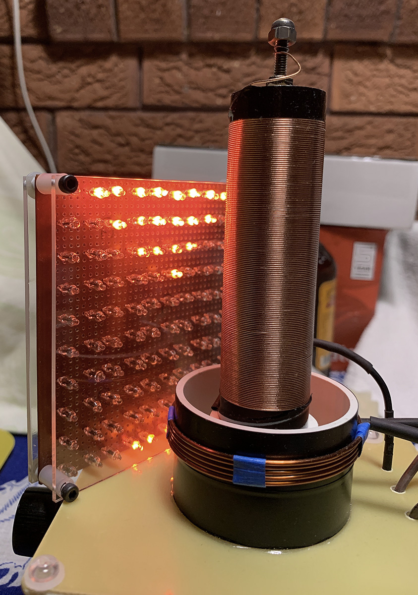
The resonator coil itself consists of around 150 turns of 0.5mm wire, wound on a 26.9mm PVC form and a winding height of 82.2mm. The overall height of the form is 106.2mm to allow for clearance and mounting. The winding dimensions resulting in a 3.07:1 aspect ratio.
The calculated resonant frequency is 10.117MHz and an inductance of 0.168mH, however, once the resonator was wound and measured, its final resonant frequency was measured at 8.50Mhz using a signal generator and oscilloscope.
For the to discharge point of the coil, a stainless-steel bolt with a brass dome nut is employed. The temperatures produced by the discharge is enough to be able to melt the copper wire.
The primary coil consists of 5 turns of 1.32mm diameter enamelled copper wire wound on a 55mm diameter x 35mm high form. The resonator coil is installed inside the primary and designed with a modular approach (can be removed).
The winding of the secondary was completed on 9th February and left overnight for the coatings of electrical varnish to cure.
The following day, the main components of the coil were placed together to test the overall design prior to commencing the build of the driver board.
A high frequency solid-state Tesla coil (HFSSTC) is a continuous wave device that operates at much higher frequencies than a traditional Tesla coil, in the vicinity of 10 MHz. The solid-state aspect of the device is that a MOSFET is used as the main switching device as opposed to a vacuum tube traditionally used in a vacuum tube Tesla Coil (VTTC).
A continuous wave coil operates at 100% duty cycle, i.e its output is a continuous sine wave, resulting in a silent operation. An interesting phenomenon of high frequency high voltage is its ability to produce a flame discharge in which the plasma discharge takes on that of a candle flame. However, producing a stable flame, this is actually tricky to achieve due to the fine line of tuning required.
To produce the necessary RF power, a Class-E RF power amplifier circuit is used. Such a circuit is able to achieve highly efficient switching using a MOSFET through the technique of Zero Current Switching (ZCS), that is, the MOSFET is switched when current flowing through the oscillator is at it's minimum point.
Below is the schematic for the circuit that is used. Click image to view at full size.
NOTES:
ZD1 is a 12V Zener diode used to limit the voltage at the gate to 12V, the TVS diode is used to protect the gate of the MOSFET.
C3 is a multi-mini capacitor (MMC) and is constructed using 4 150pF 2kV pulse rated film capacitors to give a total of 150pF at 4kV.


The key switching device is the IRFP260N, 200V 50A N-Channel MOSFET.
As part of the design, the connection to the MOSFET was made to allow for ease of replacement in the event the device fails.
For additional information on the IRFP260, I have made available the datasheet for download.
Datasheet:
The driver board layout was designed so it was able to be mounted inside the heatsink, together with the control potentiometer, the primary and resonator coil then mounted on a piece of FR4 (blank PCB) that would then been secured to the heatsink as a complete module.
L1, which is the RFC inductor is hand wound 24 turns of 0.5mm enamelled copper wire for an overall inductance of 10uH. This is the black cylindrical component on the board.
First power tests on the module completed on 15th February 2021.
For the first power-up, the circuit was connected to a 12V SLA battery without the resonator coil connected. A small neon was used to confirm operation of the primary coil.
Following the successful run, the next task was to obtain some initial measurements of current draw and initial operating frequency.


With the secondary resonator coil connected, and the circuit running, a small discharge was observed and the ability to light up a CFL lamp at a distance.
Using an oscilloscope, the mesured signal at the gate of the MOSFET was 6.7MHz. The secondary coil measured 7.74MHz.


On 16th February 2021, further testing was conducted by increasing the input voltage to 24V from two series connected batteries.
An increase in the discharge resulted and successfully observed the flame discharge characteristic. It was noted that there was some sensitivity in the adjustment of the potentiometer, and found at if turned too far, L1 would fail together with the MOSFET.
I continued testing to gain a feel for the tuning, eventually after three failed MOSFETS and 4 rewinds of L1, determined the cause of failure due to the ability of the batteries to deliver in excess of 20A.
On 18th February 2021, the circuit was powered from a regulated 32V 5A bench power supply. This now resolved the issues with burning up of L1 (due to MOSFET failure). Current was limited to 3.5 Amps for all runs.

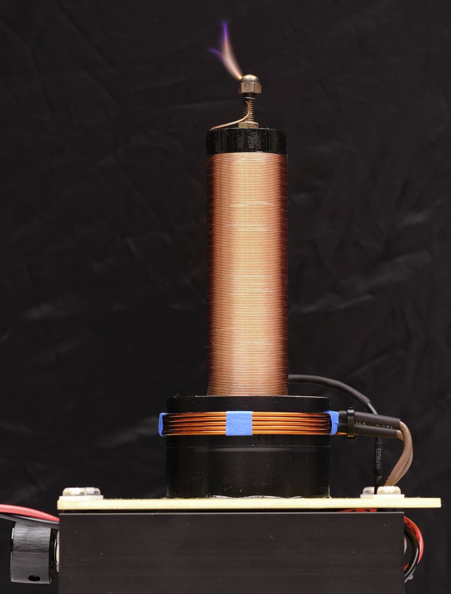
On 28th February 2021, further fine tuning of the top discharge point was undertaken. A brass acorn (dome nut) was installed on the stainless-steel screw. This addition resulted in further stability of the discharge and a much more well-defined flame discharge.
The measured operating frequency of the secondary is 7.37MHz

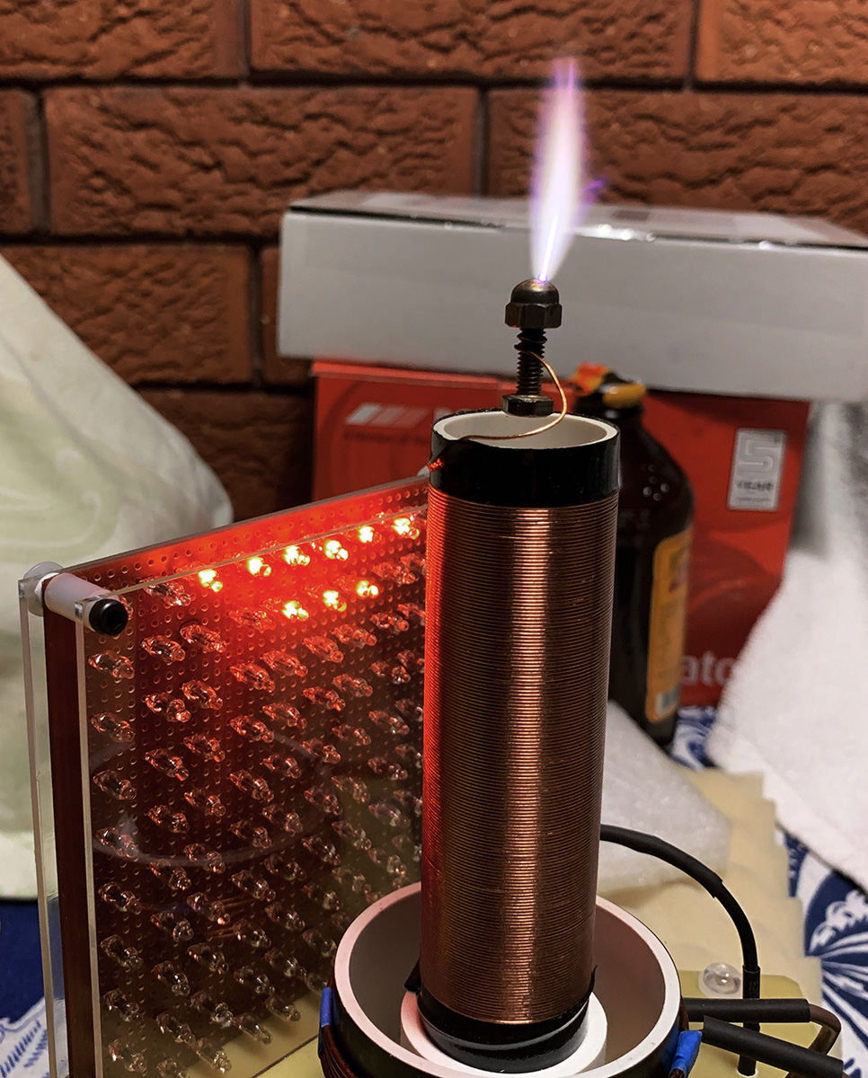
The image below is a photo of the characteristic plasma flame discharge which is the result of high frequency, high voltage.
The input was set at 32VDC @ 3.0 Amps (96 Watts), the resulting flame reaching just over 5cm.

On 21st August I had completed a Neon matrix display and conducted some tests with the coil.


As I write this update, the HFSSTC project will become a featured article in upcoming issues of Silicon Chip Magazine, at this stage slated for February 2022.
As part of preparation for the article, I can have a series of images of the coil, driver board and of the coil running.
Full technical documentation of the project is being prepared and will be released following publication.
Download Videos
A series of videos has been made available as a guide on the performance of the coil. Please note, the zip file is 79.8 MB in size.


- Flavio Spedalieri -
Written: 11 March 2021
Updated: 12th November 2021
This Document Complies to W3C
XHTML 1.0 Strict Standards


